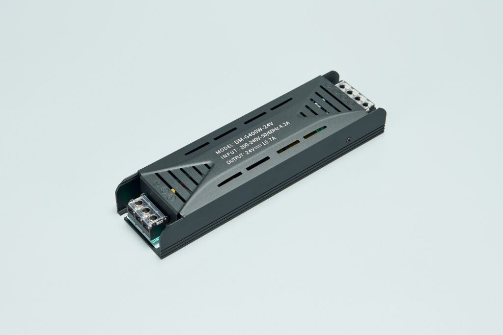
Linear power supply design involves creating a power supply that converts alternating current (AC) to direct current (DC) using a transformer, rectifier, filter, and a linear regulator. The design process typically focuses on achieving a stable and regulated DC output voltage with minimal ripple and noise. Here’s an overview of the key components and steps involved in designing a linear power supply:

1. Transformer Selection
- Purpose: The transformer reduces the AC voltage from the mains supply (e.g., 120V or 240V) to a lower, safer level (e.g., 24V or 12V AC).
- Considerations: The transformer’s output voltage, current rating, and power rating must be suitable for the intended application.
2. Rectification
- Purpose: Converts the AC voltage from the transformer into pulsating DC voltage.
- Components: Typically uses a diode bridge rectifier, which consists of four diodes arranged in a bridge configuration.
- Output: The rectified voltage is still pulsating, with a peak voltage equal to the transformer’s output voltage (minus diode voltage drops).
3. Filtering
- Purpose: Smooths out the pulsating DC voltage to produce a more stable DC output.
- Components: Uses capacitors (usually electrolytic capacitors) to filter out the AC component of the rectified voltage.
- Effect: The filter capacitors reduce the ripple voltage, which is the AC component remaining after rectification and filtering.
4. Linear Regulation
- Purpose: Maintains a constant output voltage despite variations in input voltage or load current.
- Components: Uses a linear regulator, such as the LM78XX or LM79XX series, which dissipates excess power in the form of heat.
- Feedback Loop: The regulator senses the output voltage and adjusts its internal circuitry to maintain the desired output voltage.
5. Heat Dissipation
- Importance: Linear regulators can generate significant heat, especially at high output currents.
- Solutions: Uses heat sinks to dissipate the heat generated by the regulator. The size and design of the heat sink depend on the power dissipation requirements.
6. Safety and Protection
- Fuse: Protects the circuit against overcurrent conditions.
- Overvoltage Protection: May include components like zener diodes or voltage regulators with built-in overvoltage protection.
- Isolation: Ensures electrical isolation between the input and output, reducing the risk of shock or ground loops.
7. Testing and Verification
- Load Testing: Tests the power supply under various load conditions to ensure stable output voltage and current.
- Ripple Measurement: Measures the ripple voltage to ensure it meets the specified requirements.
- Efficiency Testing: Measures the power supply’s efficiency, which is the ratio of output power to input power.
Design Considerations
- Efficiency: Linear power supplies are typically less efficient than switch-mode power supplies due to heat dissipation.
- Noise and Ripple: Linear power supplies tend to have lower noise and ripple than switch-mode power supplies, making them suitable for sensitive applications.
- Cost and Complexity: Linear power supplies are generally simpler and less expensive to design and manufacture than switch-mode power supplies, but may require larger heat sinks for high-power applications.
Conclusion
Designing a linear power supply involves careful selection of components and consideration of various factors such as efficiency, noise, ripple, and safety. By following the steps outlined above, a stable and reliable linear power supply can be created for a wide range of applications.
